Roland MDX-20 Serial Bridge (and custom enamel pins)
Not a pinned post.
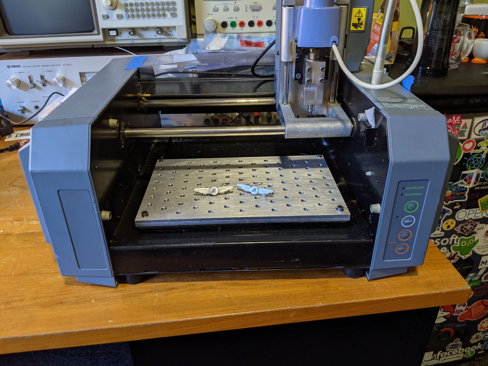
Last November, my friend acquired a Roland MDX-20 desktop router from a Media Lab reuse pile. It seemed to be in working order - it homed when powered on and the buttons on the front panel worked. Unfortunately, the router communicated with a host over a RS-232 interface, which don't exist on modern computers anymore. For future ease of use, I wanted to be able to send programs over USB. USB-to-RS-232 converters exist, but I didn't want to have to use a dedicated cable. I also wanted the opportunity to add in additional features later (tool height probing, jog pendant), so I decided to see if I could bypass whatever transceiver that was in the router and use a Teensy as a USB to TTL serial bridge.
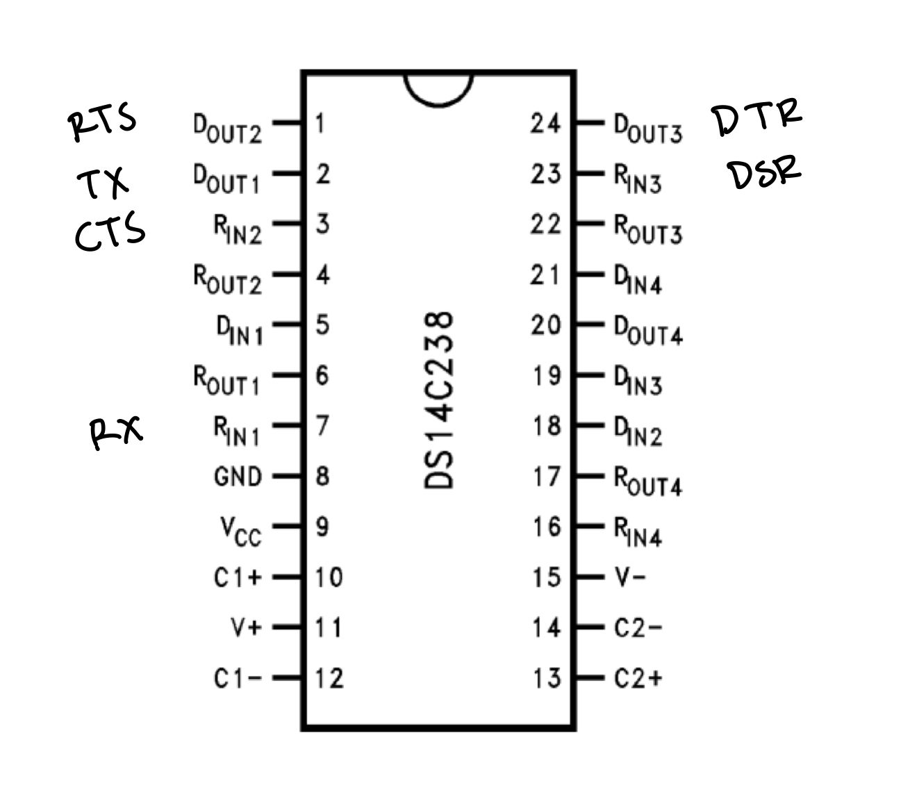
Removing the right side shell revealed the main PCBA, with the only component of interest being a DS14C238 RS-232 Driver/Receiver. Using the specified pinouts for a DB-25 RS-232 connector and the connector on the board, I was able to trace which of the inputs and outputs of the transceiver on the microcontroller side corresponded to which signals. I then removed the transceiver to prevent it from interfering with the Teensy (transceiver pulls pin low but Teensy tries to pull pin high, etc).
To connect the Teensy to the board, I tried soldering wires directly to the newly exposed IC pads, but ripped a couple of the pads off in the process. I found that all of the signals that I was interested in eventually crossed to the other side of the board through vias, so I was able to solder wires through the vias instead of on the pads, which greatly increased the mechanical strength of the connection.
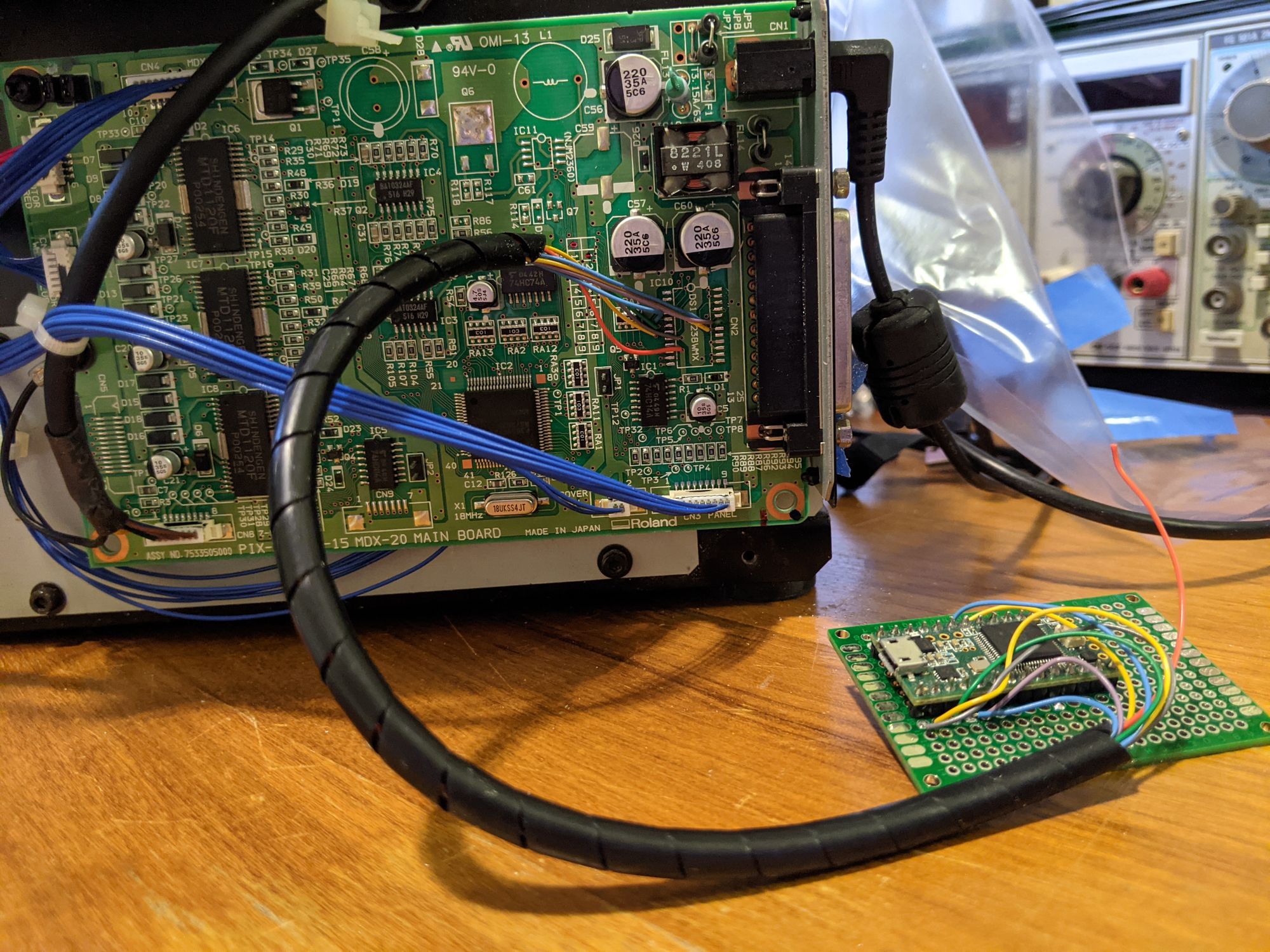
The Teensy implements hardware flow control with the DTR pin from the router, and software flow control with the host computer, preventing both the router's internal buffer and the Teensy's serial buffer from overfilling. A python script takes files from a CAM postprocessor in the RML (Roland Machine Language) format, and sends them character by character over the USB serial port to the Teensy.
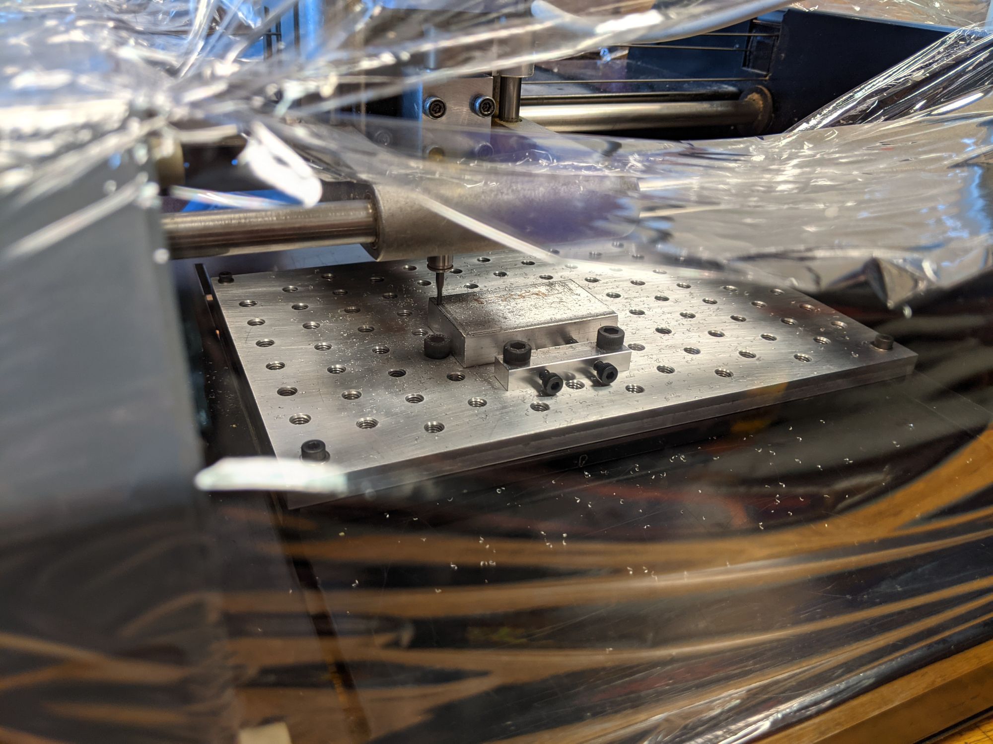
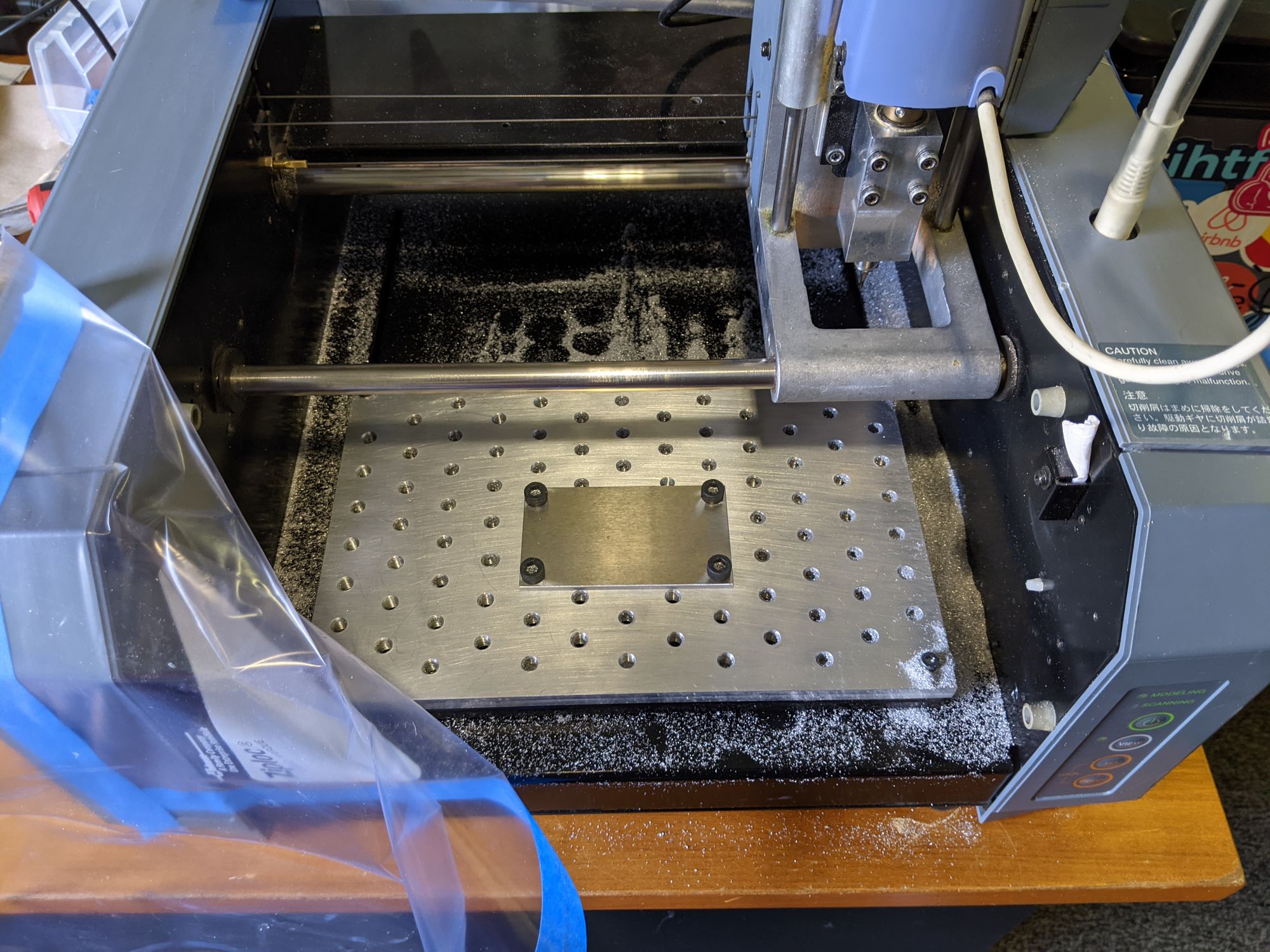
There is no way to set XY work offsets in RML, so all absolute movement commands sent need to be relative to the machine origin. However, you are able to set the Z offset. To locate stock or flipped parts in the machine workspace, I made a fixture plate, similar to the threaded fixture plates offered by Carbide3D and Bantam Tools for their desktop CNC routers. My fixture plate had a staggered grid of M6 tapped holes spaced 0.75" apart, which seemed like a good compromise between fixturing flexibility and number of holes. I also made a couple of simple mounting clamps so that I could fixture material without using bolt holes or masking tape/CA glue. These clamps push stock against the heads of some bolts that are threaded into the plate, clamping the stock in place.
Through a couple of test cuts, I was able to find the XY location of the machine origin relative to the fixture plate, and use this location as the XY origin for all CAM setups.
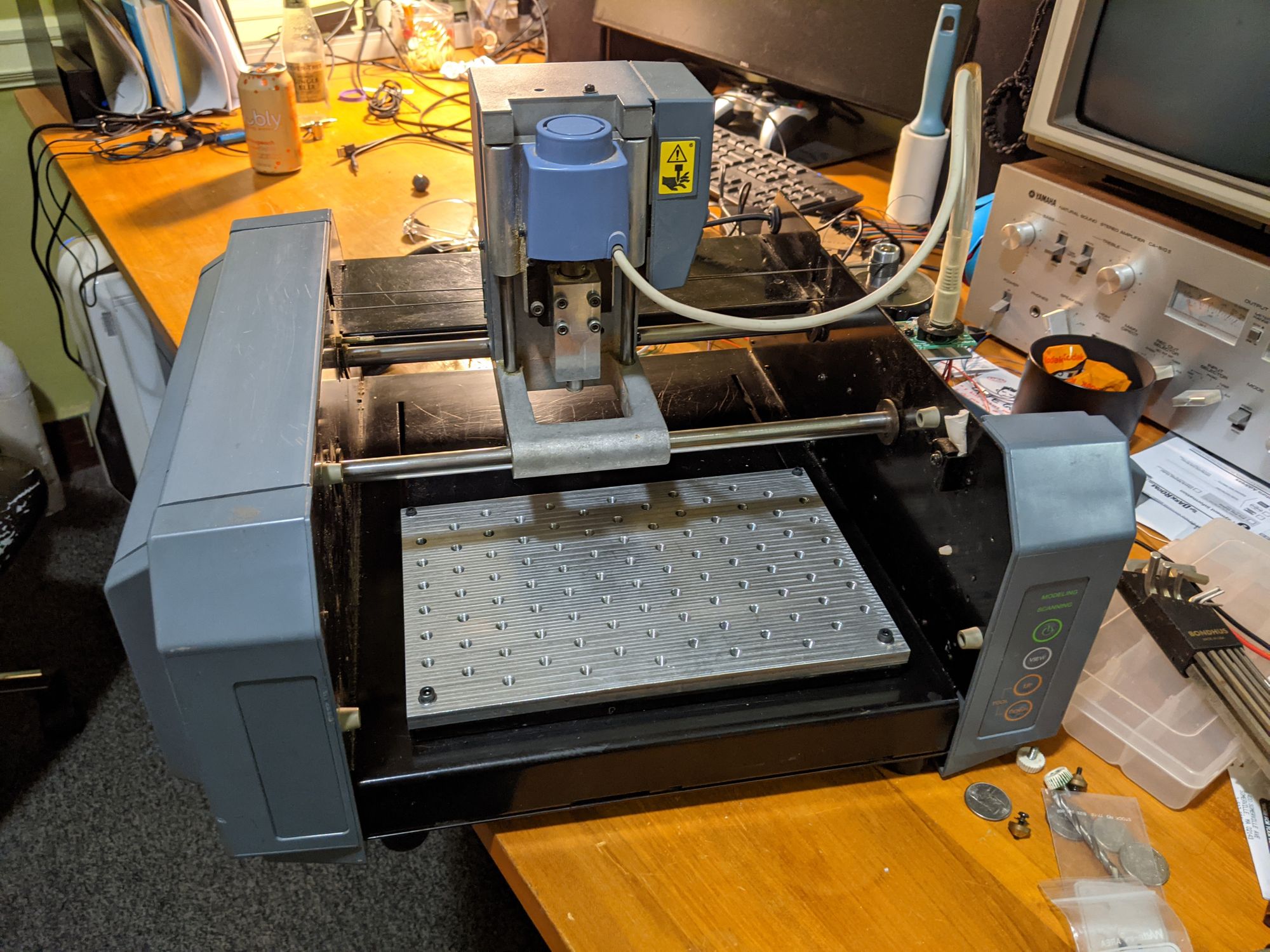
I tensioned the cable drives for each axis, and it was ready to use!
My team for 2.009, the mechanical engineering capstone class, wanted to make some gifts for our team instructors. Our project was an aisle wheelchair that would reduce the amount of physical interaction needed between the wheelchair user and the flight attendant during transfers of the wheelchair user between the aisle wheelchair and the airplane seat. Because of the airline connection, we decided to gift them pilot pins with our product logo. A teammate designed the pins in Illustrator, and I used that design to make a 3D model, which I created toolpaths for and ran on the MDX-20. Most of the pin was machined in two large adaptive operations, one with a larger 3/32" endmill and one with a 0.02" endmill. After these operations, there was a final contour to part the pin from the rest of the stock. I attempted to do the contour with the smaller endmill first, but after snapping two of them, switched to the larger one. I suspect that the runout of the spindle was too large for slotting with the 0.02" endmill, as a single endmill as able to easily make it through the entire adaptive toolpath, which had a stepover of less than half the endmill diameter and no slotting. Otherwise, the feeds and speeds were the same between the two toolpaths.
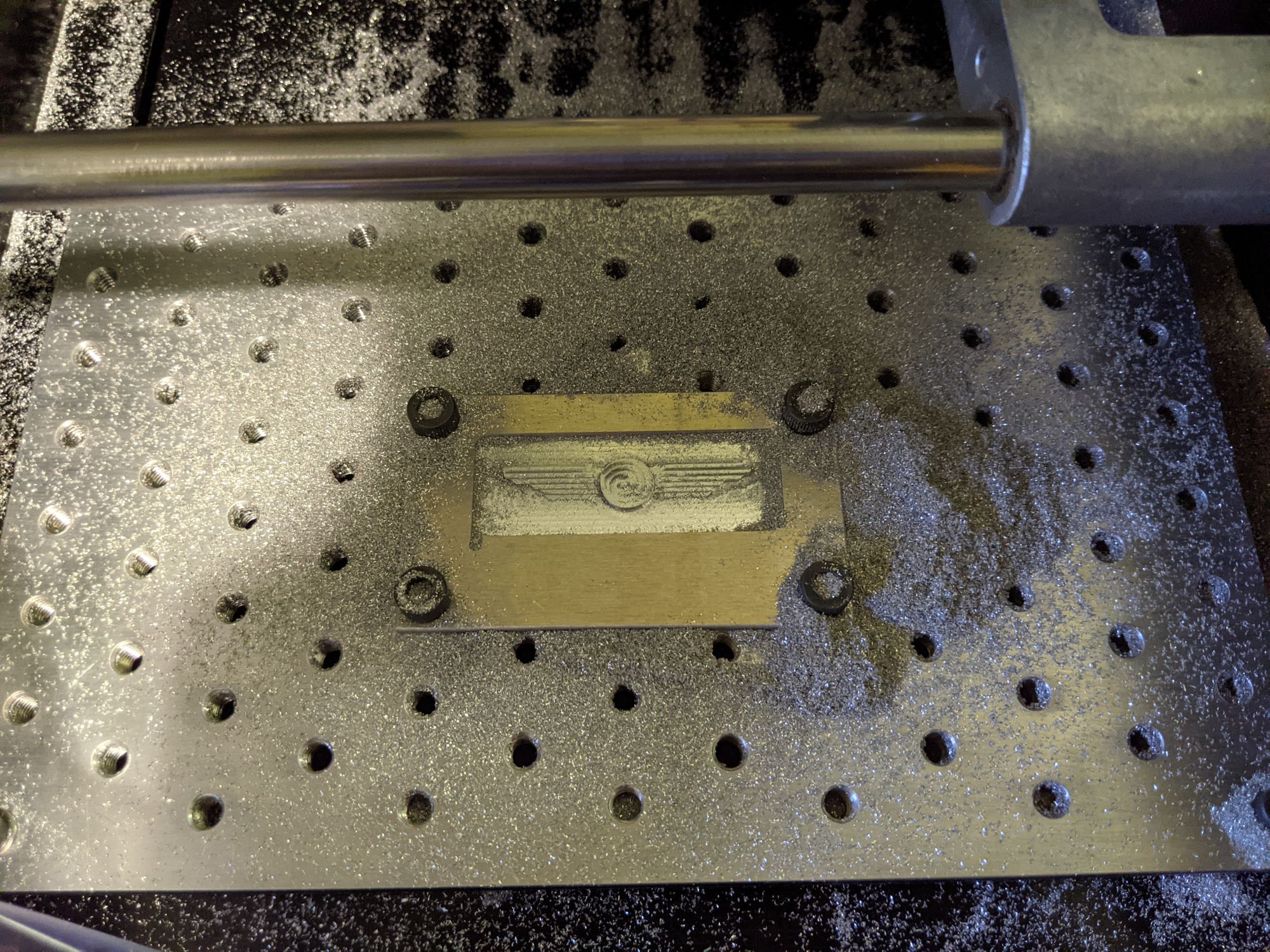
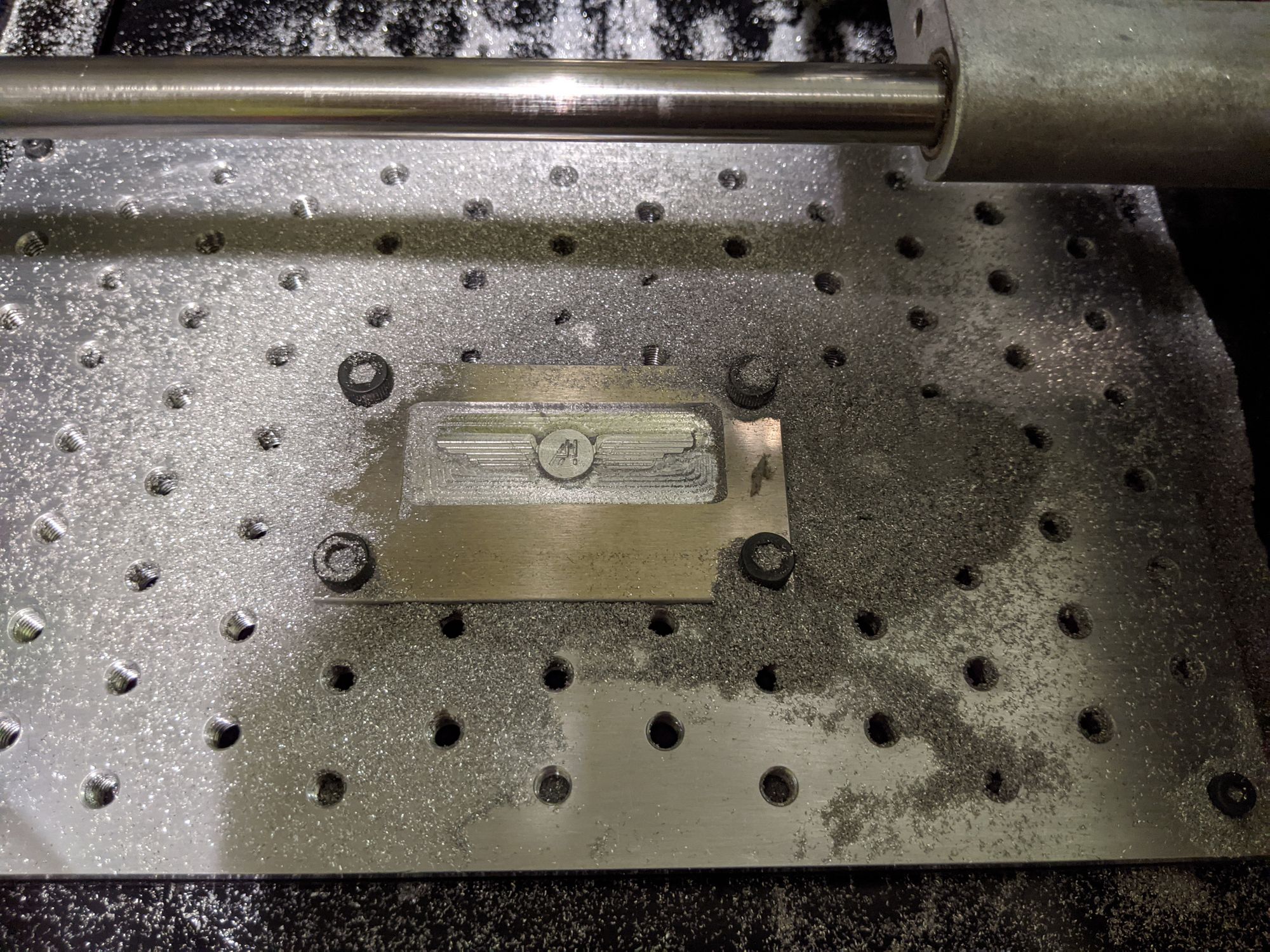
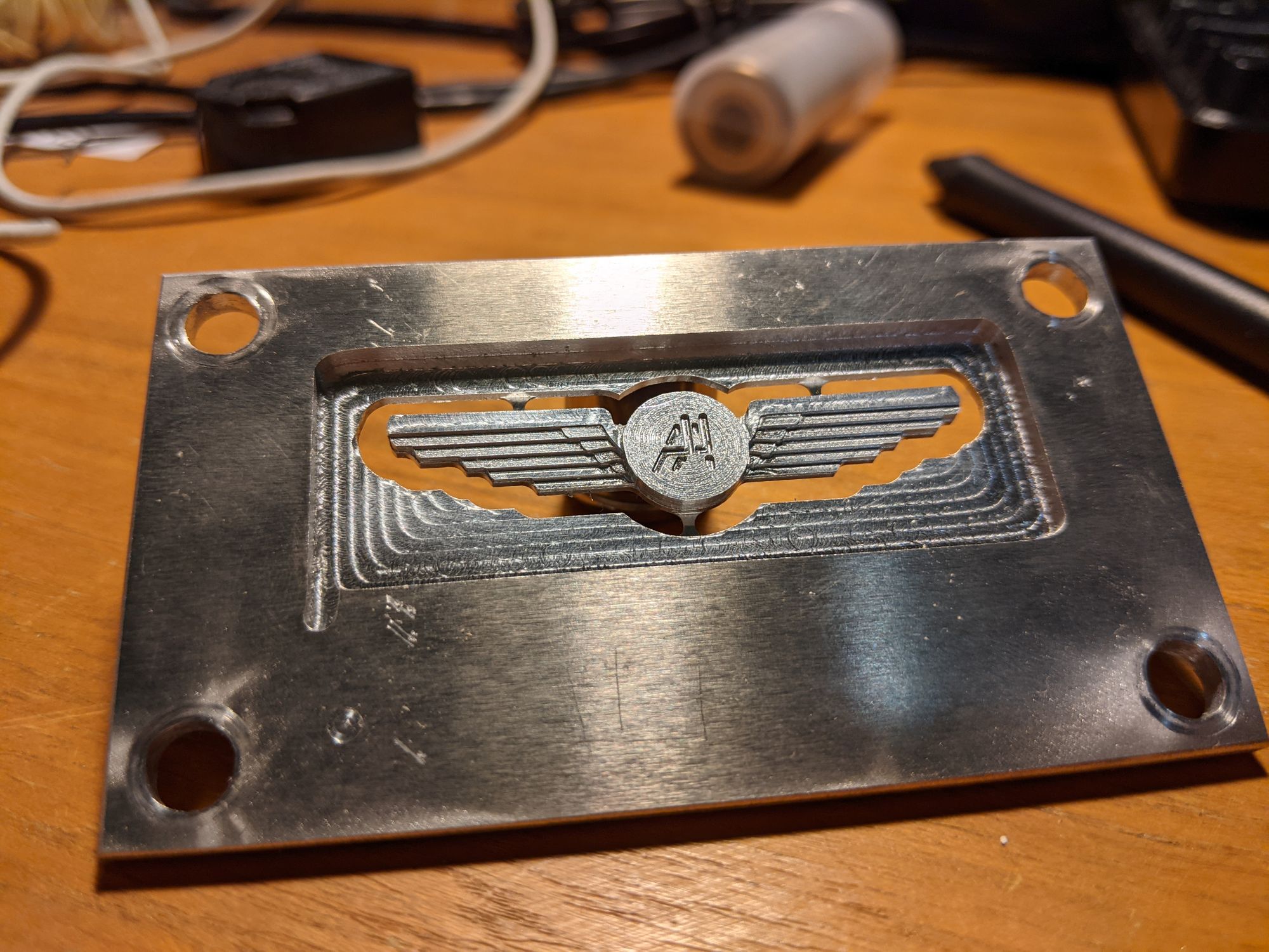
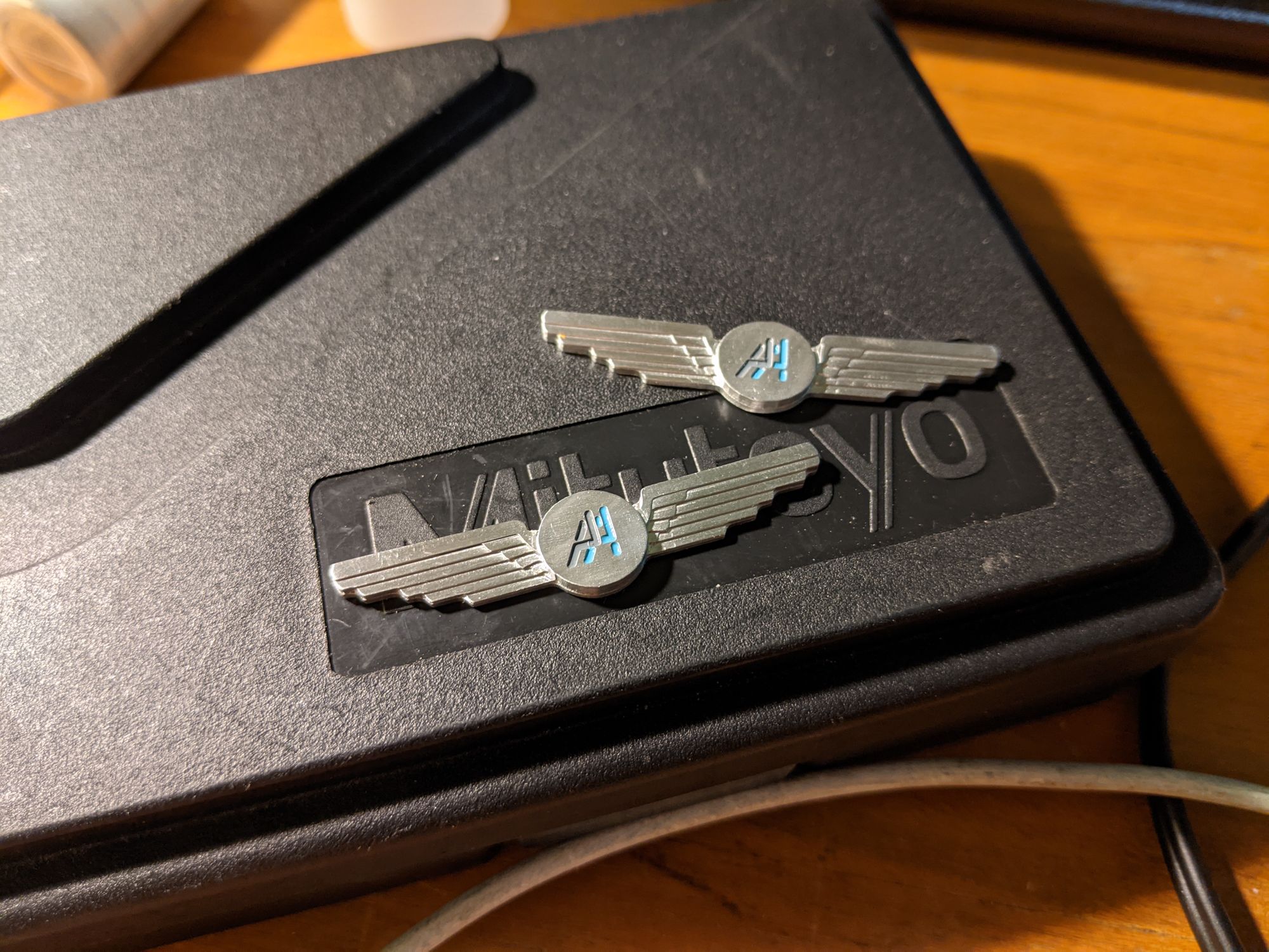
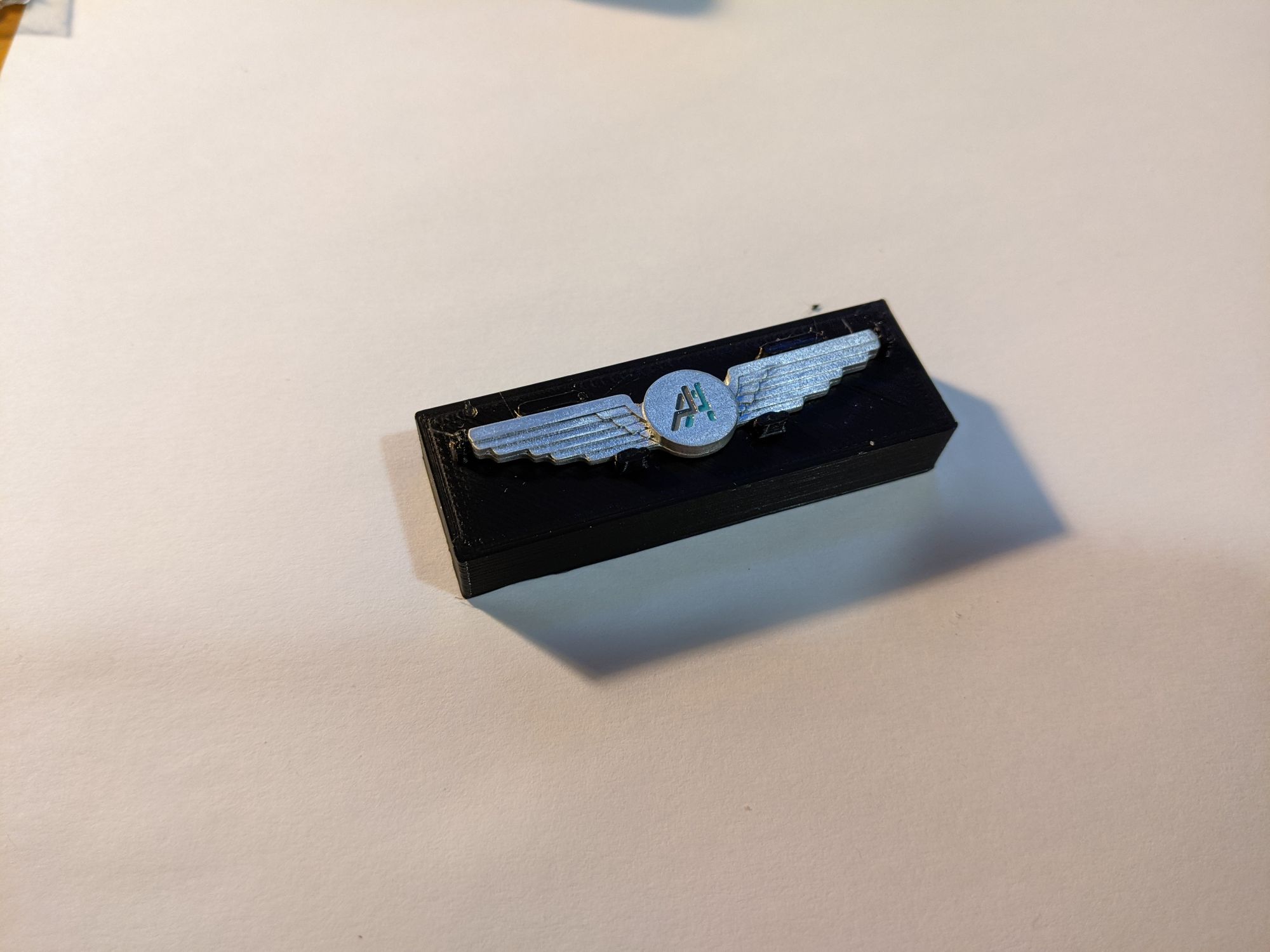
The logo was recessed into the pin, and I filled the pocket with soft enamel paint. I then polished the pins, applied a couple layers of clear coat, and made and used a 3D printed jig to glue on the pin studs.
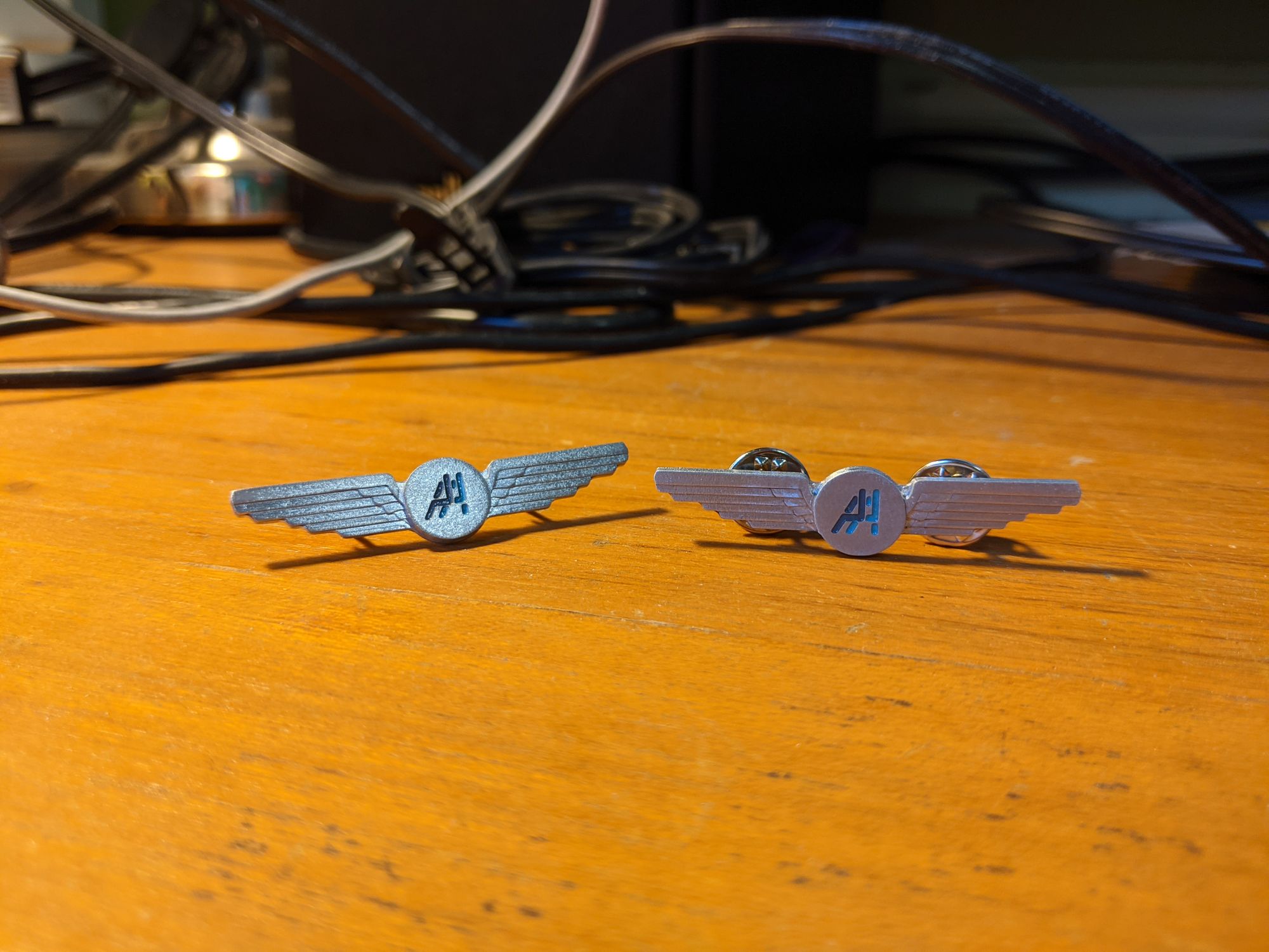
Overall, I think these came out well. The material remove rate is a bit slow, but this should be bearable for smaller parts. With some more tuning of feeds and speeds and a spindle upgrade to reduce runout, the router will be a nice addition to my set of tools.