seesaw: a 3 DOF seesaw?
1 more than last time.
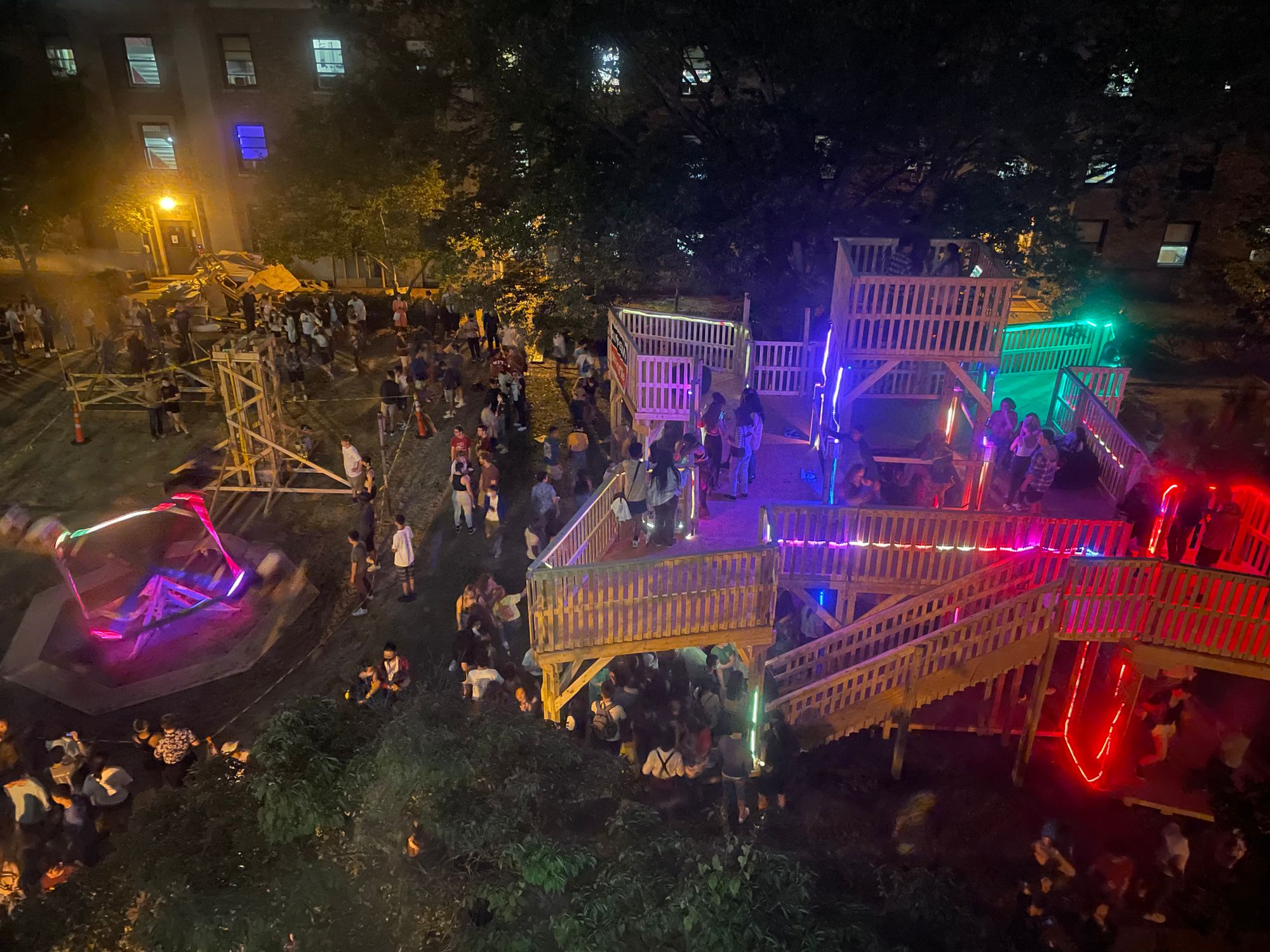
As is tradition, East Campus builds a bunch of temporary wooden structures at the start of fall semester for the incoming freshmen during Residence EXploration. In previous years, students have made wooden roller coasters, large rotating climbing walls, and a large trebuchet. In 2019 my friends and I made a 2 degree of freedom swing, so I decided that we needed to step it up for our last year. How do we make the ride more intense? By adding another degree of freedom.
We decided that the easiest degree of freedom to add was another rotational degree of freedom, as adding translational ones tend to be much trickier. This was important to keep the project on time and viable, as our team was also smaller this time around.
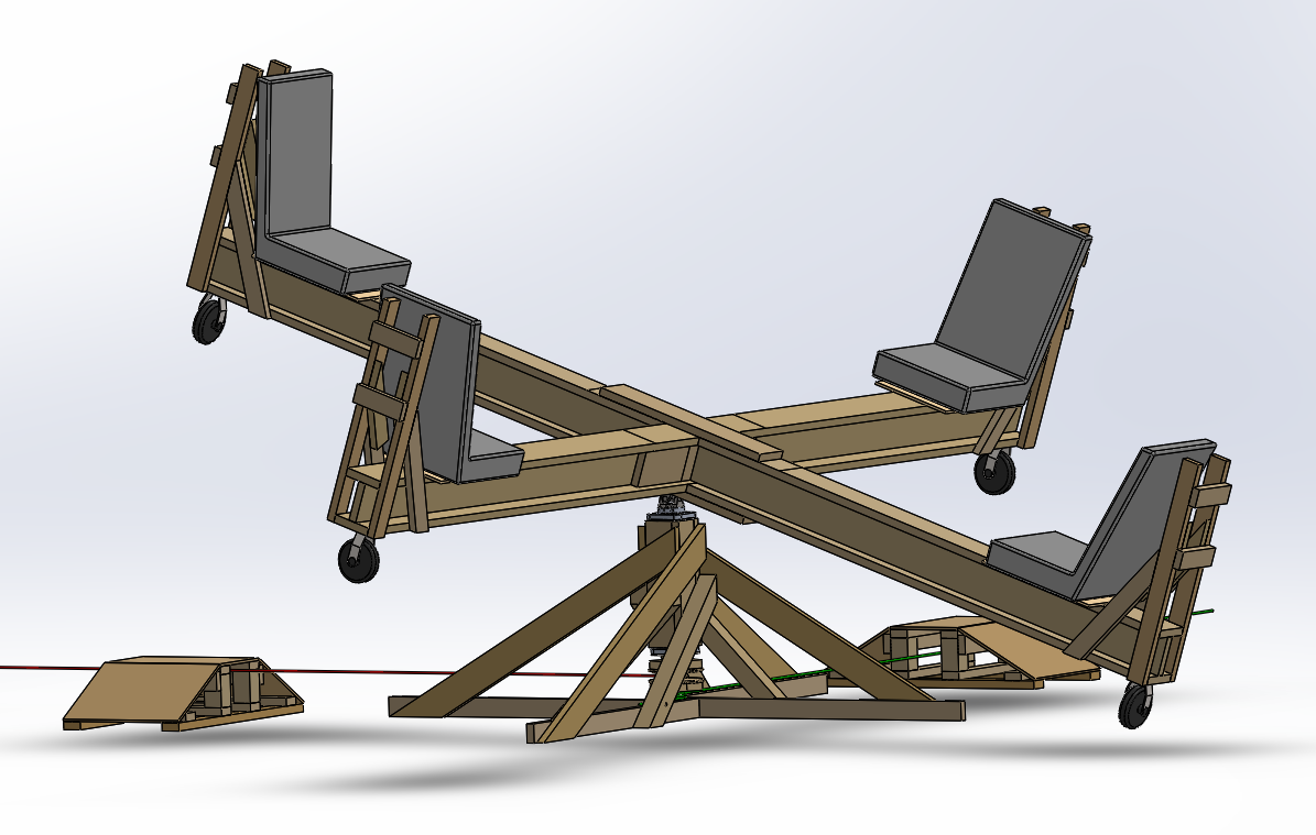
Learning from past mistakes, we started the design and analysis far ahead of the deadline for submitting our documentation to the structural engineer. We decided on a design that looked like two normal seesaws attached perpendicular to each other and supported from the underside by a small wooden structure. This left us the opportunity to expand our design with a gravity battery, which would drive the yaw rotation through a rope and pulley system.
While looking for sources of cheap but large universal joints to provide the roll and pitch rotations, I discovered the existence of cheap, non-OEM truck universal joints. These joints are meant to transmit torque from the driveshaft to the rear differential and are large, made of steel, and relatively cheap. We settled on the universal joint from a Toyota Tacoma, as they seemed to be readily available and would easily support our expected load of 4 people. The top of the seesaw is rigidly attached to one side of the universal joint, and the other side of the universal joint is rigidly attached to a tube that acts as the shaft for the yaw rotation. The shaft is axially supported by a 511946/910 taper roller bearing, and both radially and axially supported by the taper bearing and a 6213 deep groove ball bearing. The taper bearing is only preloaded with the weight of the riders, which is above the minimum load required by the bearing. The bearings and shaft are much larger than they need to be due to constraints on the size. This had the side effect of making it so that the bearing and shaft setup didn't really have to be changed if the gravity battery was added in.
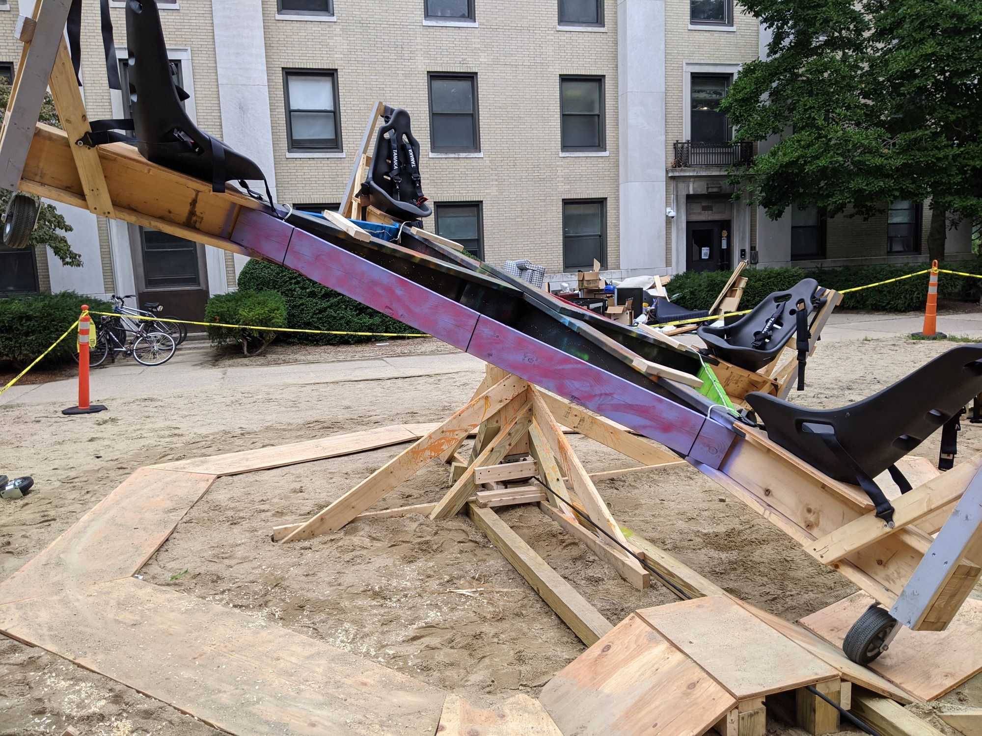
To save costs, we decided to use the same bucket seats that were used in wAo, with a similar harness mounting configuration. Rigid pneumatic casters would be attached underneath the seats to prevent them from rubbing on the ground while the ride was rotating. We chose a seat to opposite seat distance of 18ft, giving ample distance between riders in case there were any covid related distance restrictions.
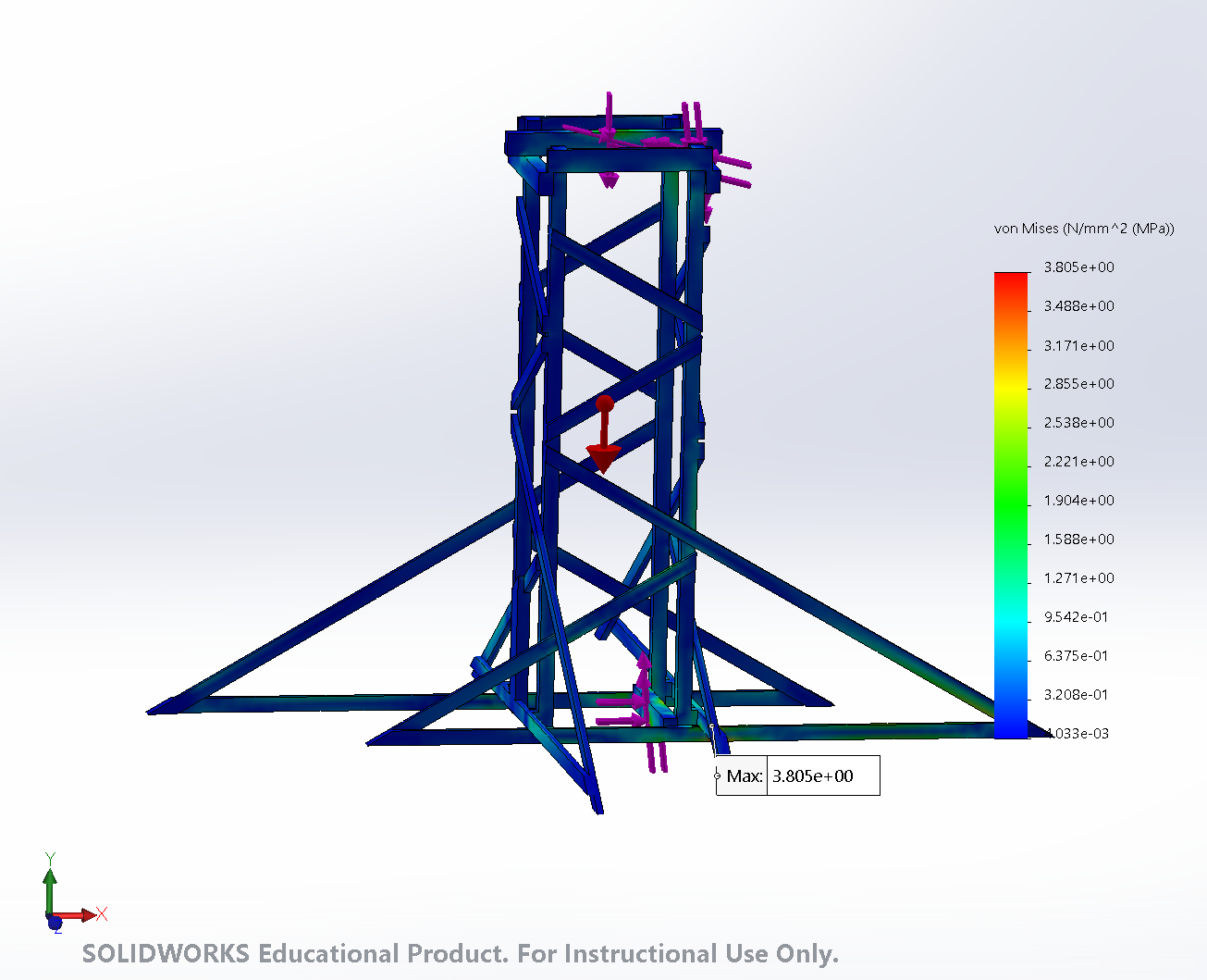
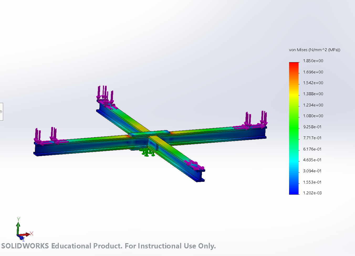
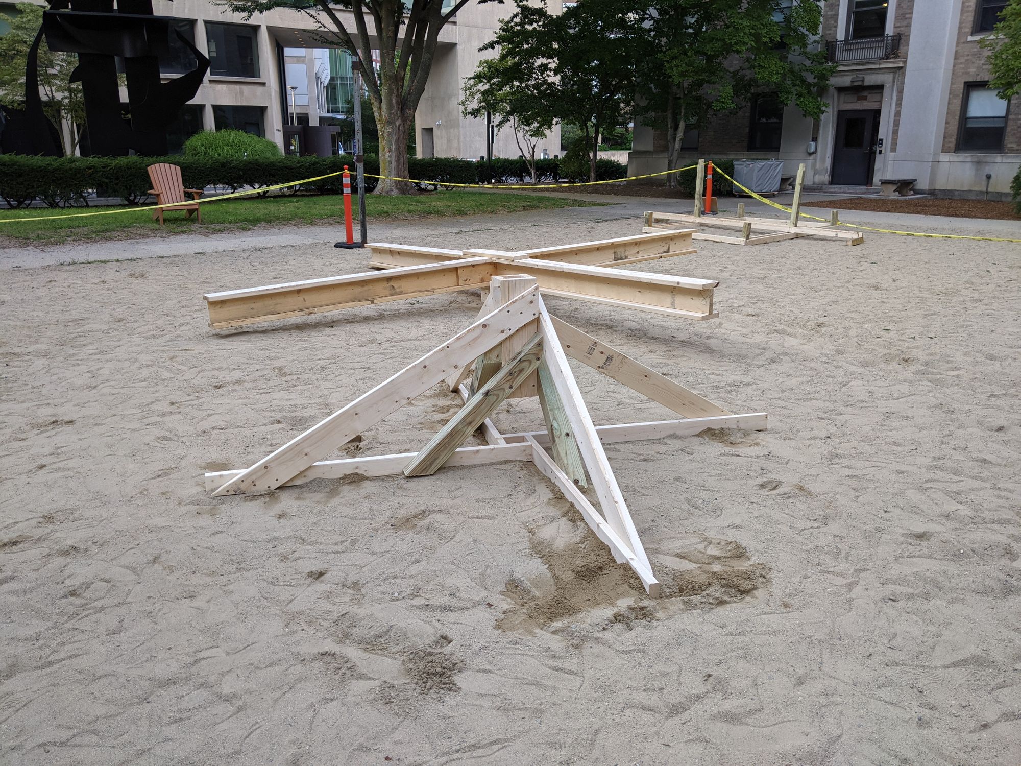
Now that the critical dimensions and parts were chosen, we just had to connect them all together. At the time, wooden I-beams seemed like a good choice to connect the seats in a cross, and a simple box with some braces to the ground to hold the shaft bearings. I did hand calculations to determine the wood dimensions needed, with a large safety factor for impact loads. After putting it all together and running some FEA to make sure that everything was ok, the seesaw looked like this. While designing the ride as a whole, I was sure to try to keep the loading in the direction of the wood grain, as that is the direction that wood is strongest in. Because of this, for the FEA and hand calculations, I used the values of the relevant properties in the direction parallel to the grain (compressive ultimate strength, flexural modulus, etc). Since the compressive ultimate strength is lower than the tensile ultimate strength, I used that as the overall ultimate strength.
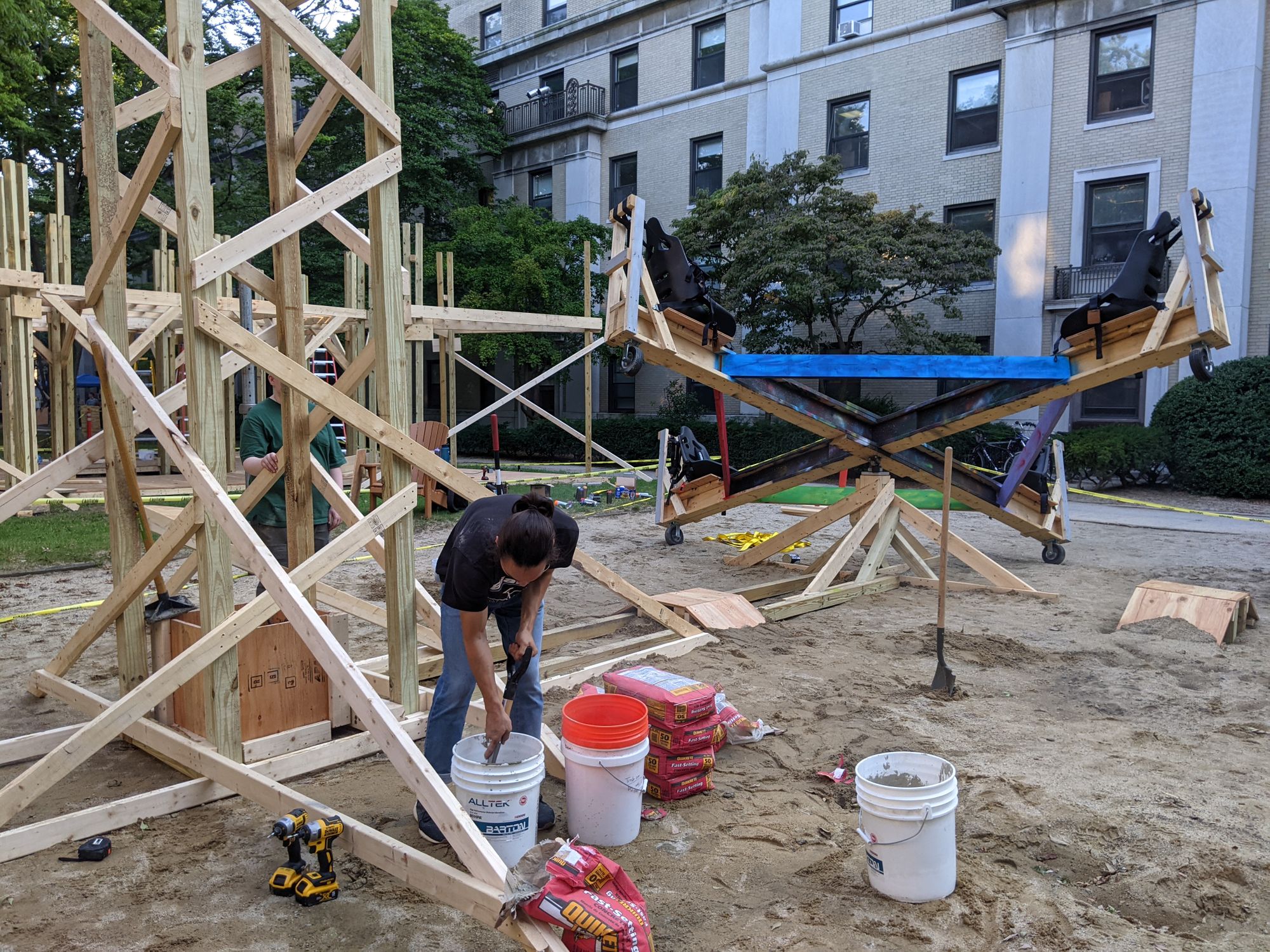
Now that we were very ahead of schedule, we were able to also design the gravity battery. The concept here is straightforward. We store energy by raising a large weight up, and the weight transfers its potential energy into the ride after it is released, spinning it. The cable guards needed also serve to induce pitch and roll rotations.
We chose a target weight of around 300kg, as in the absence of friction it would spin the seats to 20 mph. This of course was a very very optimistic estimate, as the rolling resistance of the wheels act at a large radius and dissipate a lot of power. To avoid having to stick multiple lengths of wood together, we limited the height of the tower to 12 ft. These two constraints pretty much determined the entire design. We decided to make the weight out of concrete, as it was an easily worked, dense material that was commonly available.
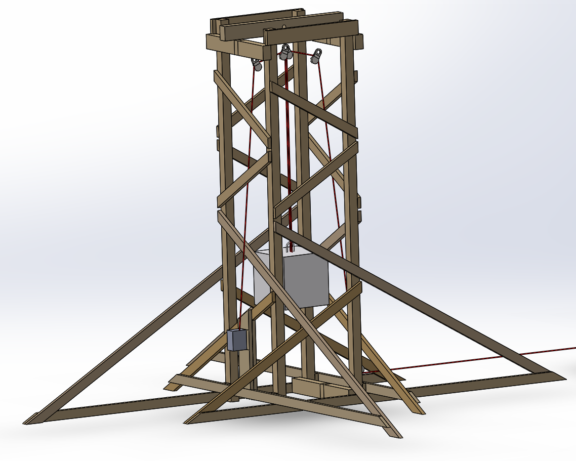
After some sketching, we came up with this. We originally wanted to use a winch to raise the weight up, which we later axed due to budget constraints and some concerns about if it would even be better than just driving the seeesaw backward. The pulleys are held to the frame with large ratchet straps, which are kept from shifting with wooden blocks.
We did hand calculations on all the non-wooden components as well as the wood structures. The calculations for the structures were supplemented with some FEA, and found that it was all fine. However, the boundary condition for the ground was not quite right, as it was a stiff elastic support. This is not representative of the real world because the ground cannot "pull" on the structure. However, the areas farther away from the support will not be affected by the exact nature of the support due to Saint Venant's Principle, which means most of it is correct.
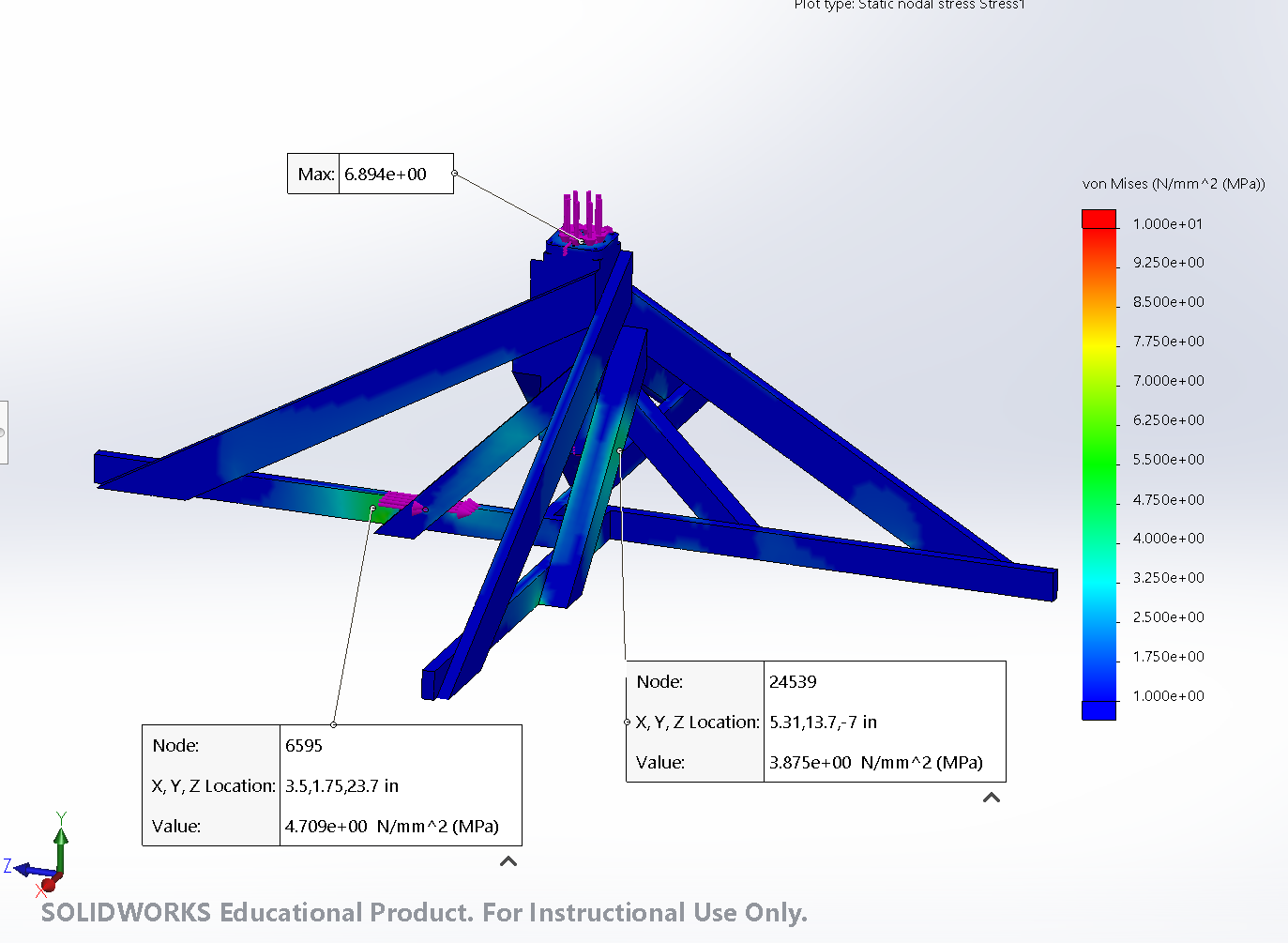
The strut going between the seesaw and the gravity battery to hold the two structures apart was not modeled. I did a buckling and bending hand calculation to verify that it wouldn't instantly break and left it to figure out during construction, as we didn't realize that we would need this strut until wood had already been ordered.
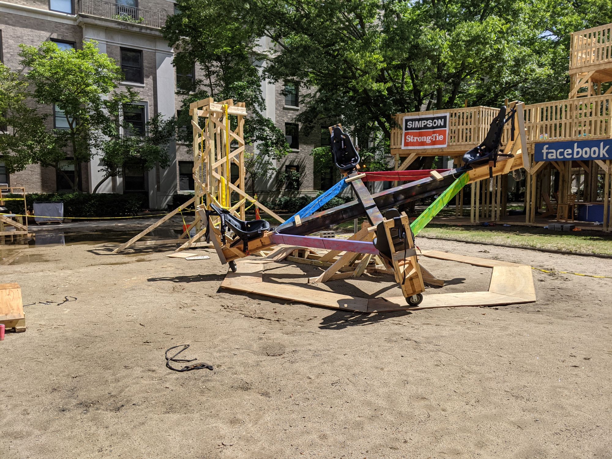
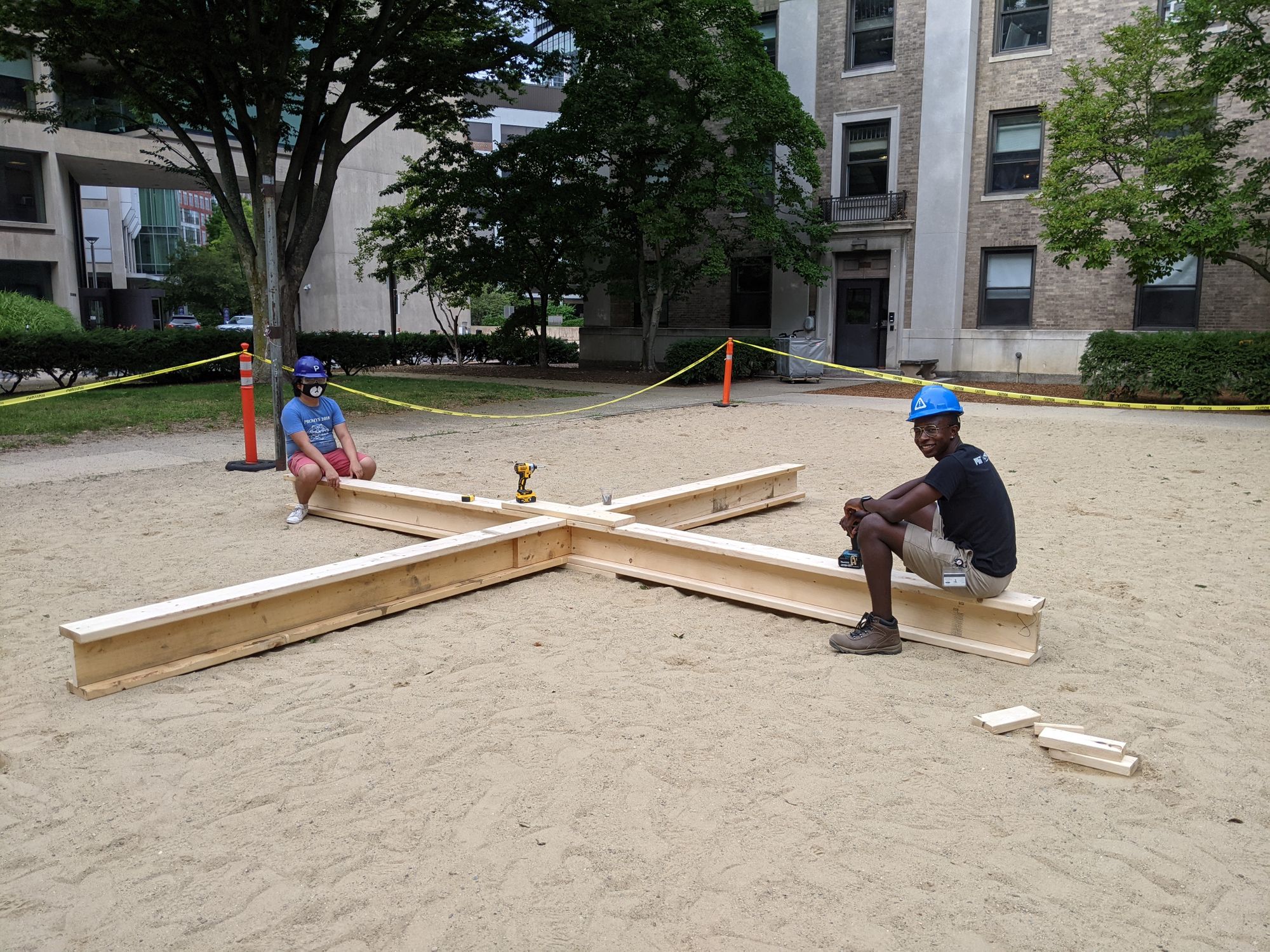
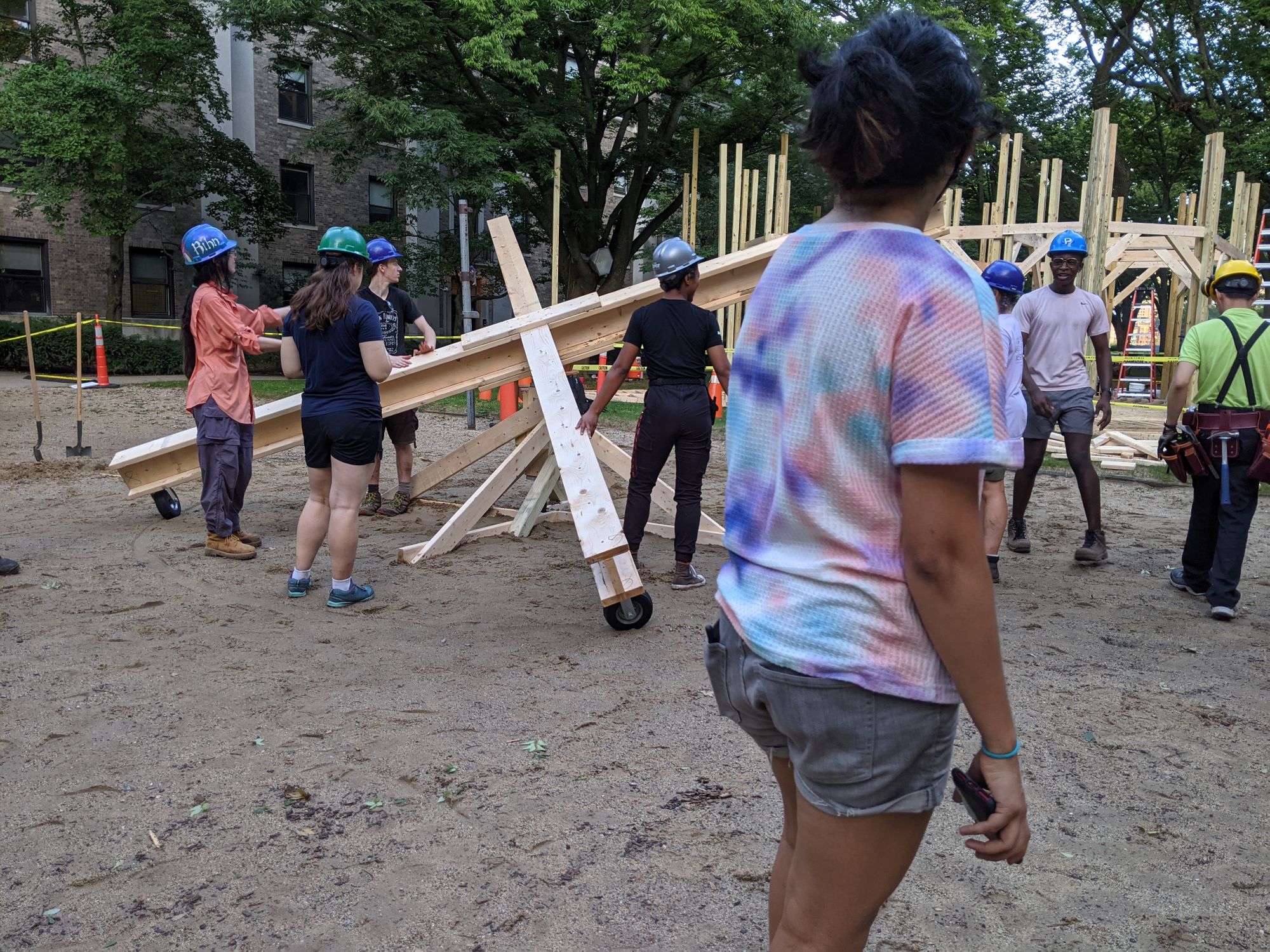
Construction was pretty straightforward. We discovered quickly that we would need to add braces between the arms of the seesaw, as impacts with the ground while the ride was spinning added a moment load parallel to the long axis of the beams, twisting them. We also added a plywood track for the wheels to ride on because there was too much friction when rolling on sand. This greatly increased the speed of the ride.
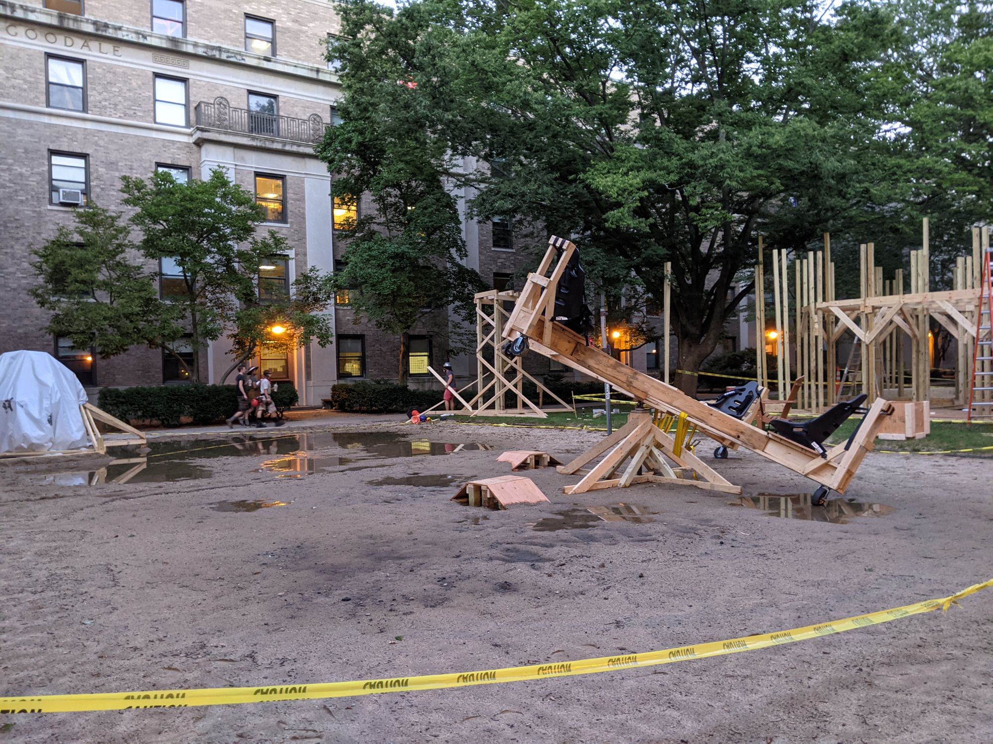
Similar to wAo, we had some cracking on the vertical 4x4s used in the gravity battery which we discovered prior to the East Side Party. Because of the rain in the prior days, I believe these cracks were from the expansion and contraction of the wood. This is supported by the fact that cracks did not propagate more throughout the operation of the ride. We had an issue with the rope fraying and breaking at the spool, due to rotations of the spool relative to the shaft that it was on. The spool was clamped to the shaft by the tension in the rope. However at the end of the ride, the rope goes slack and allows movement of the spool. This would have been solved with more preload on the rope or a secondary clamp to keep the spool from rotating relative to the shaft while the rope was slack. Luckily, the rope broke while we were winding up the gravity battery before the weight left the ground.
Overall, the ride was successful. We ran it throughout the entire East Side Party for over 5 hours, serving approximately 300 people.