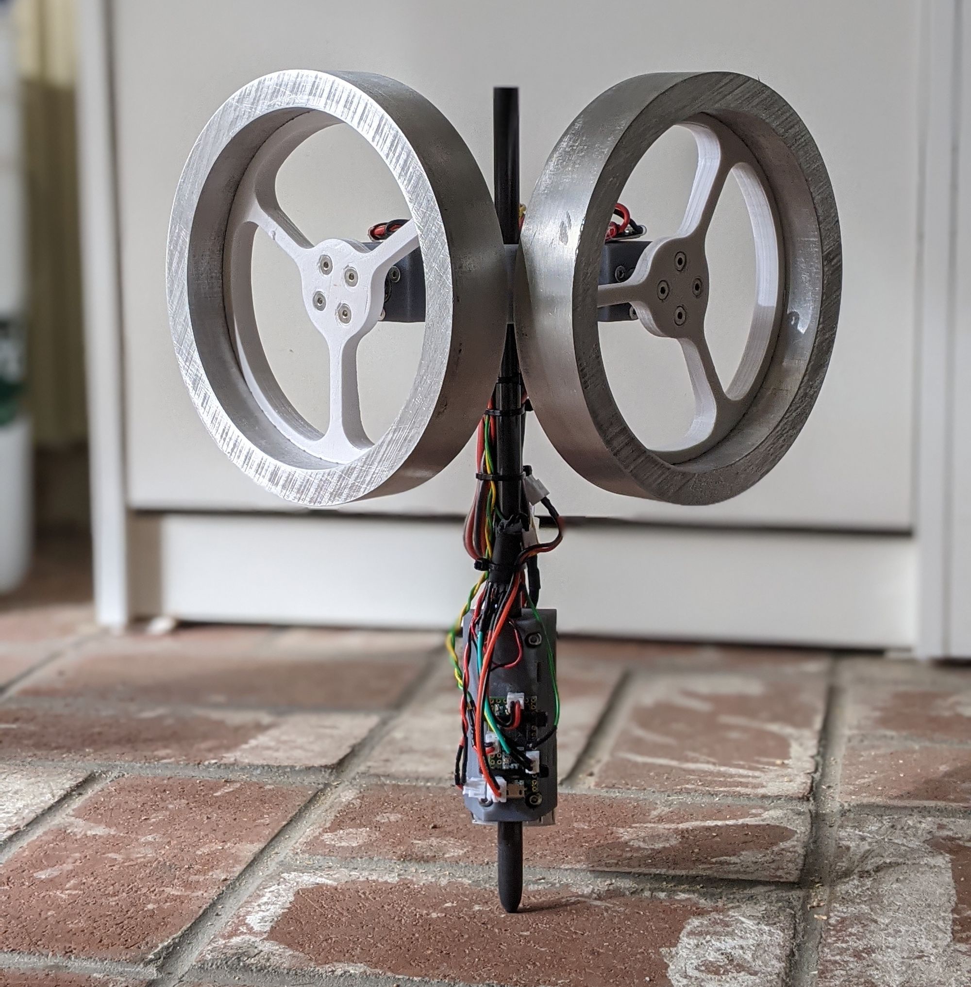
Reaction Wheel Balancing Stick
STICKO MODE
I've been taking a lot of controls classes recently, and I decided that I wanted to put some of the techniques that I learned to use in a project.
After digging through the Internet, I found this project. This stick was tethered, and ran two PID loops to stabilize roll and pitch, with yaw uncontrolled. I thought it would be an interesting design challenge to integrate all the electronics onto the stick itself, and to use some of the new state space control methods that I had been learning.
I got some extra DJI M2006 gearmotors and C610 ESCs from my friend Nathan, who was using them for low-cost quadrupeds. These ESCs are controlled over CAN and support torque control, which make them very convenient for controls projects.
I started by deriving the some simplified equations of motion. In 3D, the roll and pitch axes are coupled together through precession. This is complicated, so I decided to treat each axis independently, as if it was only in 2D. By doing this, we end up treating the coupling as a disturbance, which should be rejected by the controllers. I derived the equations of motion for a 2D inverted reaction wheel driven pendulum using the Lagrangian.
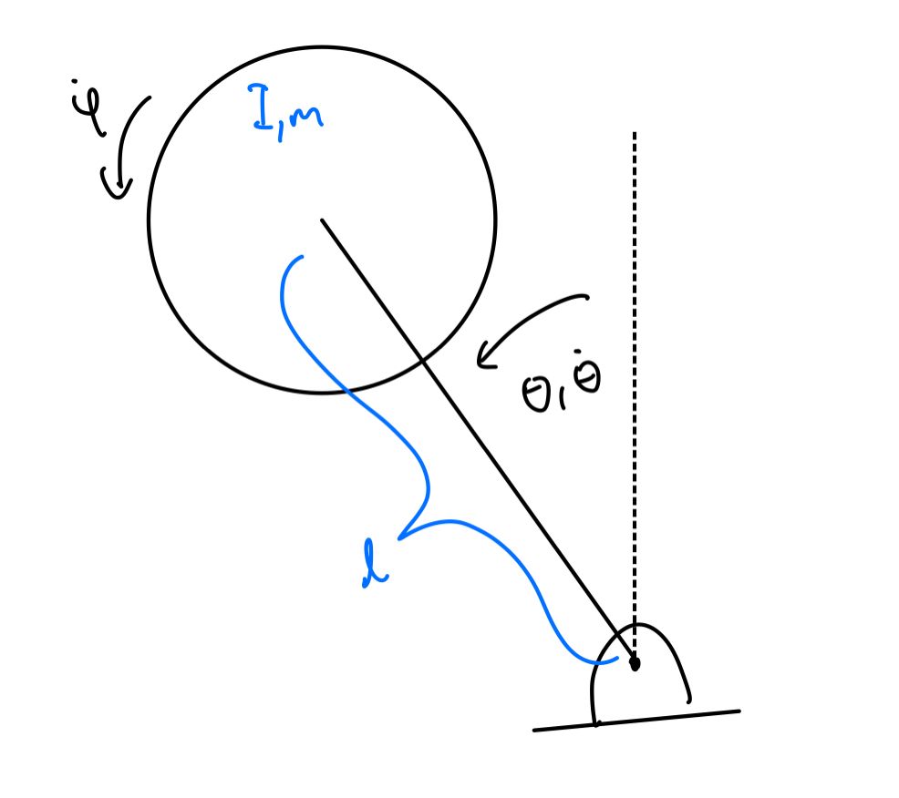
Using the equations of motion, I was able to get an estimate for the sizes of the wheels, length of the pendulum, and target mass. To maximize the amount of control input that the controller can apply, we want the inertia of the flywheels to be as large as possible. This is because the flywheels accelerate as torque is applied, and once the no-load speed of the motor is reached, no more torque can be applied. However, we want the equivalent mass at the end of the pendulum to be as small as possible, as a large mass would result in a larger inertia, which would result in an increase in the torque needed to accelerate. A longer pendulum length does the same thing.
Using this model, I implemented an LQR controller, where the states of the system were [theta, dtheta, dphi]. By choosing these states, by controller vaguely looks like a PD controller with some extras. My input and output weights were vaguely based on the maximum torque that the motor could exert and the maximum desired angle and flywheel speed.
I was then able to choose the flywheel inertia, equivalent mass, and stick length by repeatedly simulating the initial condition response of the system, and checking to see if the actual motor I was planning on using would exert the torque needed, and if the flywheel speed saturated.
I was then able to start on the rest of the physical design. This was relatively straightforward. I didn't spend a ton of time trying to minimize the mass of the parts, as it would just result in a slight decrease in the set of initial conditions that the controller could stabilize the system from. I mounted the battery and microcontroller near the base of the stick to minimize their effect on the inertia, but left the motor controllers on the top for ease of packaging. One important design insight was that the stick should go through the center of mass when perpendicular to the ground, so that equilibrium point is close to "upright".
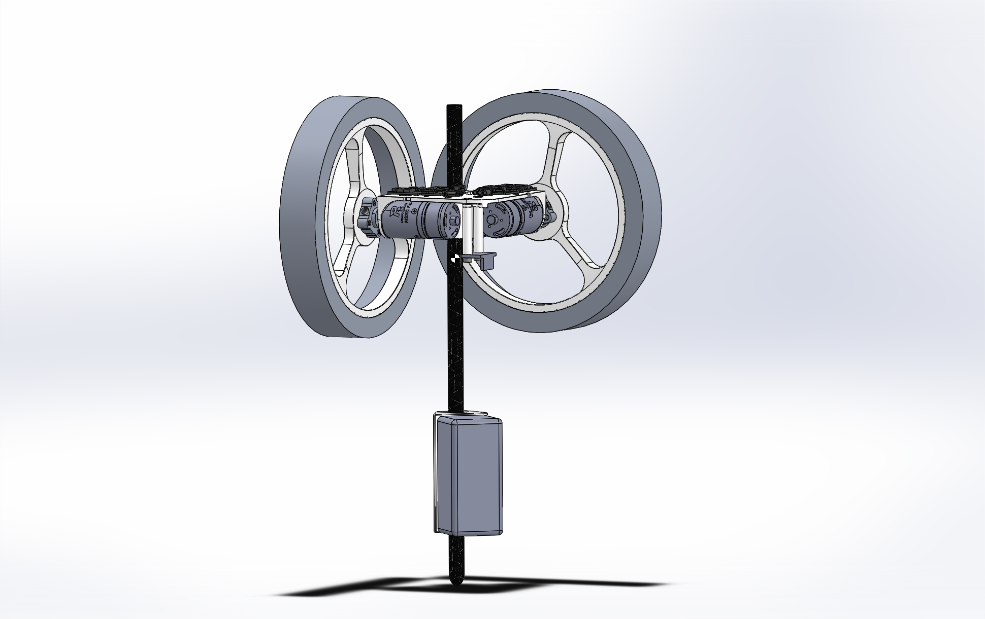
I designed it so that the flywheels consisted of a short length of aluminum tube lightly pressed onto a 3D printed inner piece. This makes it so that if there are undesired collisions with the flywheel against the ground, the tube slips on the printed parts, reducing the impact on the motor shafts and the rest of the assembly. This sort of was a replacement for not having a good way to safely hold the stick while testing the controller.
Most of the parts were printed on a Form 2 in Grey Pro, as I happened to have the printer to make parts for a research project. The rest of the parts were printed in PLA.
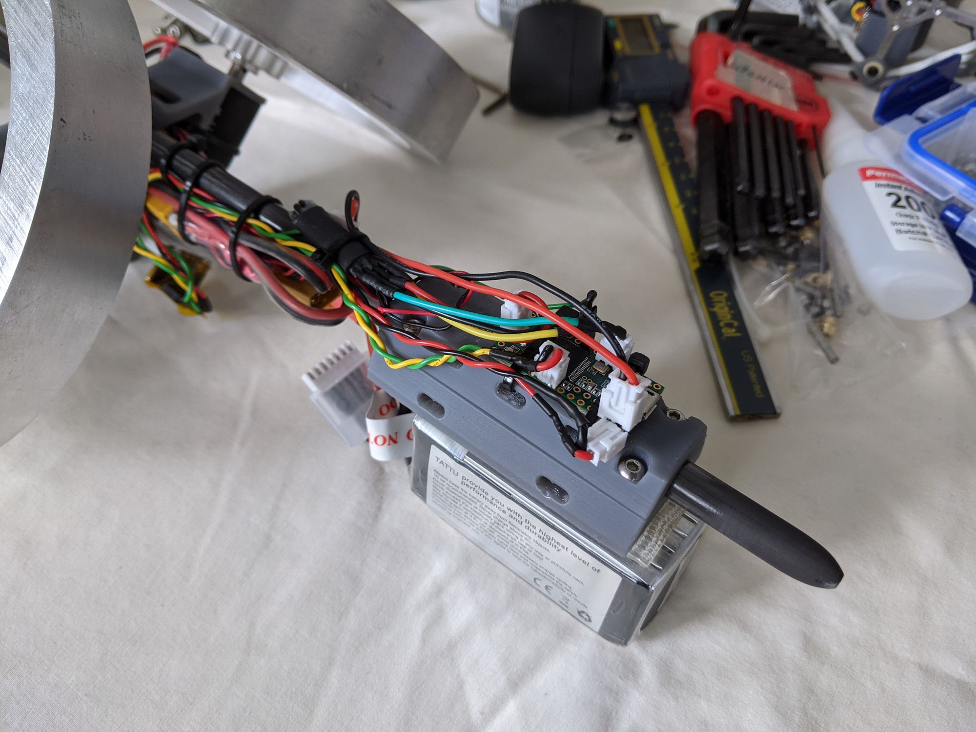
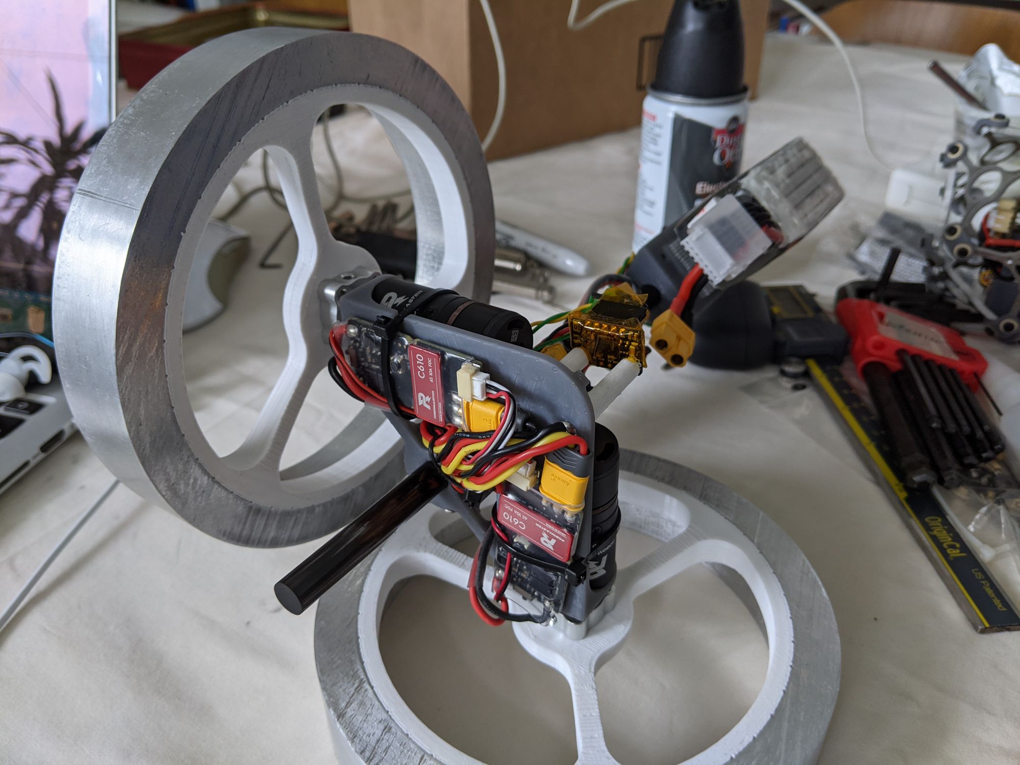
A Teensy 3.2 ran the control loop, with a bunch of mildly messy point-to-point wiring to the ESCs through a CAN transceiver and the IMU (MPU6050). A small 6S battery was attached with Velcro on the other side of the stick to the Teensy, and powers the Teensy through a linear regulator. This battery turned out to be enough to run the stick for a pretty long time, as the motor power draw is not very large once the stick is near the equilibrium point.
I wasn't able to stabilize the stick with the initial LQR controller. I eventually figured out that it was because of three things. The IMU was picking up a lot of noise from the motor controllers switching, so I added some standoffs to move it further away. The gyroscope values (dtheta) from the IMU were also very noisy, so I reduced the gain acting on those terms. Finally, I added an integrator on wheel velocity to drive the wheel velocity to zero at steady state.
This controller is actually pretty neat. Because of slight misbalances and errors when calibrating the IMU, the unstable equilibrium of the stick is not where the IMU says the roll and pitch angles are zero. Because of this, the controller would have to constantly exert at torque to stay at the origin, eventually saturating the flywheel speed and failing. The flywheel acts as an integrator on motor torque. If there is a large enough gain on flywheel velocity, it will force the commanded torque to zero in steady state before the flywheel velocity saturates. However, this means the flywheels are spinning at steady state, which is undesirable because we are part of the way to saturation. To remedy this, we add another integrator on the flywheel velocity, which will drive the velocity to zero at steady state as well.