Electric Moped Motor Mounting
Motor mounting and more!
I've always wanted to make some sort of small electric vehicle, and since I made some money over the summer (yay jobs!), I decided to pull the trigger once I got to MIT.
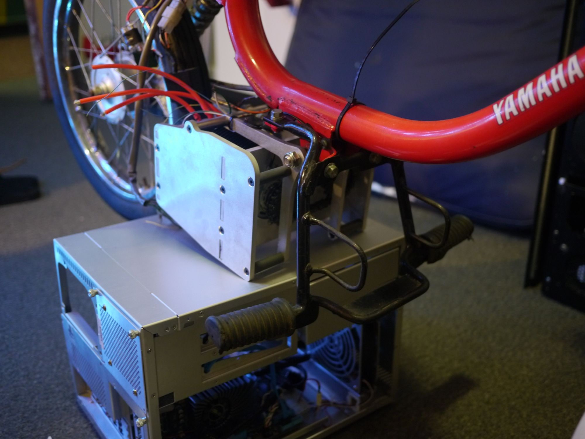
Because I was edgy and didn't want to build a scooter like literally everyone else on hall, I picked up a Yamaha QT-50 off of Craigslist. Produced from 1979 to 92, stock QT-50s come with a 49cc 2-stroke reed valve engine driving a cantilevered rear wheel through a total reduction of 13.78:1. Unlike many other mopeds, QT-50 is shaft driven, which ended up simplifying the motor mounting for the replacement motor.
The engine is part of the swing arm for the rear suspension and needs to pivot on the bolt in the front. I removed this entire assembly from the moped and detached the engine from the transmission, while retaining as much of the transmission as possible. Because the engine was pretty tightly integrated with the first two reductions, I was only able to use the last 5.69:1 bevel gear reduction attached to the rear wheel. Luckily, this last section was broached for a square drive shaft, so I was able to design a corresponding drive component and simply bolt the section onto whatever motor mounting design I came up with.

Retaining the pivot and suspension geometry, I came up with the above design. It has a Neumotor 4415, which I picked out of the spare parts shelf at Kitty Hawk, driving the transmission drive shaft with #35 chain through a 1:1 "reduction". The motor sports a still untested external hall effect resolver that I printed in order to avoid having to open up the motor and glue hall sensors inside. Instead of using turned shoulders to retain the shaft, I opted to use premade 3/4" keyed shaft and shaft collars. The drive shaft ends in the square drive mentioned before, with a pretty loose fit into the broached section to allow for a decent amount of misalignment.

The construction of the mounting box itself is pretty standard, with captive nuts and screws used to secure the waterjet panels to each other. With the exception of some slight tolerance mishaps (turns out aluminum sheets mill marked 0.25 aren't actually 0.25), the assembly of the motor mount was pretty straightforward. I hit all the surfaces with a 220 grit pad on the orbital sander before assembly to give it a matte finish that sorta matches with the rest of the bare aluminum on the moped. The transmission and suspension was attached without any problems, and bouncing on the seat didn't reveal any issues with the new swing arm.

The chain tension in the front is slightly sloppy, despite using ideal values for center-to-center distance. Because I didn't design in any method to adjust the chain tension, I'll have to add some sort of idler later if the tension becomes a problem. I don't anticipate this being a problem because the chain run is so short. I'll have to run the chain in and check the tension after the rest of the conversion is done. I still need to design and machine some sort of battery case, and wire in the motor controller, main contactor, and DC-DC converters to drive the lights.